
Although it was quite cold, I braved an hour or two in the garage to resolve two issues that had been bugging me: one was the data logger not logging the RPM that was being sent to it, the other was the fact that the RPM was not being correctly calculated.
Fortunately, just before I lost the feeling in my fingers, I managed to resolve both of these issues. The tacho signal is received from the Audi ECU and this is a simple square wave, or at least I believe it is, not having an oscilloscope I don’t know for sure. What I do know is that every time the engine fires a spark plug the pulse is sent, and being a 5 cylinder engine this means 5 pulses per full engine revolution. I had tried timing the pulse with pulsein (an Arduino command) but this didn’t seem to work as expected. I also originally had the pulse coming through an opto-isolator, this I have also removed, although I doubt it was an issue, just a complication. Instead of the opto-isolator I know use a voltage splitter through two resistors, calculated using this site, that takes a signal that could be between 12v and 14v down to <5v, suitable for the Arduino pin in limit. The Arduino is capable of timing on the basis of interrupts, and having read through a similar blog for timing a computer fan I used the same code for the input from the ECU. So many thanks to Chris at pyroelectro.com as I have lifted his code more or less intact and inserted into mine.
// Used for RPM

volatile float time = 0;

volatile float time_last = 0;

volatile int rpm_array[5] = {0,0,0,0,0};

//

void setup() {

attachInterrupt(0, fan_interrupt, FALLING);

}

//

void loop() {

Serial.println(getRPM());

delay(500);

}

//

long getRPM() {

int rpm = 0;

if(time > 0)

{

//5 Sample Moving Average To Smooth Out The Data

rpm_array[0] = rpm_array[1];

rpm_array[1] = rpm_array[2];

rpm_array[2] = rpm_array[3];

rpm_array[3] = rpm_array[4];

rpm_array[4] = 60*(1000000/(time*5));

//Last 5 Average RPM Counts Eqauls....

rpm = (rpm_array[0] + rpm_array[1] + rpm_array[2] + rpm_array[3] + rpm_array[4]) / 5;

}

Serial << "freq total RPM: " << rpm*2 << "\n\r";

return rpm*2;

}

//

void fan_interrupt() {

time = (micros() - time_last);

time_last = micros();

}
Now that the tacho sensing is resolved I went onto getting the data logger working. The data logger uses a high speed serial link to receive data from the primary unit as I had found i2C was unreliable, and I couldn’t be bothered to make a canbus system. As I am using an Arduino Mega I have three serial ports, one for programming, and two spare, one of these is now used for the data logger, and data is sent every 500 milliseconds.
/************************************************/

/* Dump info over Serial 3 to logger */

/************************************************/

void sendToLogger(){

if (millis() - timeVal[13] > 500){

// ***********************

// RPM value

// ***********************

int tempRPM = getRPM();

Serial3 << tempRPM << ",";

// ***********************

// Cell group StateVal

// ***********************

// Serial3 << millis() << ",";

for(int i = 0; i < StateVal[0]; i++){

Serial3 << StateVal[i] << "," ;

}

// ***********************

// Cell group TimeVal

// ***********************

timeVal[13] = millis();

for(int i = 0; i < 13; i++){

Serial3 << timeVal[i] << "," ;

}

Serial3 << "\n\r";

// The logger card will add G force and write this all to the SD card.

LEDUpdate = millis(); // move SD Update to next time interval

}

} // Void end
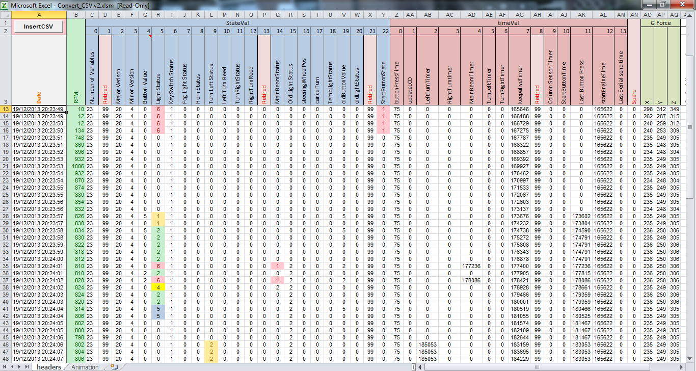
Some time ago I had already created the CSV format and created all of the code for writing to the SD card, now that this is working I have a nice readable output. The SD card I am using is 4gb and with the present format this should last for a long time as logging is about 400k per hour.