

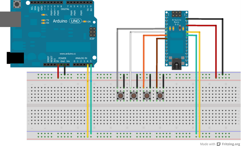
In this, the first promised post about using an Arduino in my kitcar project I will give two code snippets and a high level Fritzing diagram, along with a list of the potential projects I see for this wonderful piece of kit.
In the Fritzing diagram I have a shown an Arduino Uno/Deci and an Arduino Nano, this doesn’t have to be the case, any pair of Arduinos, Freeduinos or Seeeduinos will work, just check the pin outs.
The Nano in the diagram will eventually be housed into the steering boss and connected to the buttons mounted on the steering wheel. This boss will also be modified to allow it to be made removable, but without having to plug things in and out. This will be achieved by modifying the existing horn contacts and adding a further two contact points, two for power and two for the I2C bus.
There is also the potential to add a small display screen into the steering wheel, or indicator LED’s. We can use the I2C interface to not only pull information from the slave unit, we can also write data to it.
As you can see, the initial project idea of using buttons on the steering wheel can evolve immensely, and it will!
Amongst the ideas I have are the following;
- Realtime Data Clock
- Data Logging to SD card
- Bluetooth connection for real time analysis
- RFID ignition
- Control of all non-essential electronics
- N+1 redundancy design
- GPS position tracking
- GSM receive/send module
- Remote start
- Gearbox control
- Fuel usage analysis
- Realtime multipoint chassis monitoring
- Interconnection to engine management system
…and that’s just the start.
For the setup shown at the top of the page I have included the code below. Program first the slave unit, and then the master unit. Run a serial monitor session connected to the master and you will get a feedback of the button status from the slave. This is step one; in step two we will start doing more interesting things.
[php]
//
// Mastercode to be used with Slave_I2C
//
// Tim Russell
// www.russellweb.eu
// Twitter: timr1972
//
#include <Wire.h>
#define SLAVE1 0x0A
int button[7] = {0,1,2,3,4,5,6};
byte rcv_bytes[2];
int draw;
//SoftwareSerial mySerial = SoftwareSerial(13, 13);
void setup() {
pinMode(13, OUTPUT);
Serial.begin(115200);
Wire.begin();
}
void loop() {
// Retrieve button values from slave 1
for (int i = 0; i <=5; i++){
i2c_communication(button[i], SLAVE1);
Serial.print(draw);
Serial.print(", ");
}
Serial.println("");
delay(500);
}
void i2c_communication(byte request, int slaveID) {
Wire.beginTransmission(slaveID);
Wire.write(request);
Wire.endTransmission();
delay(1);
Wire.beginTransmission(slaveID);
Wire.requestFrom(slaveID,2,true);
// Wire.endTransmission();
for (int i = 0; i < 2; ++i) {
rcv_bytes[i] = Wire.read();
}
bytes_to_int(rcv_bytes);
}
void bytes_to_int(byte b[2]) {
draw = (b[0] << 8) + b[1];
}
[/php]
…and the following is for the Slave unit.
[php]
//
// Slave code, to be used with Master_I2c
//
// Tim Russell
// www.russellweb.eu
// Twitter: timr1972
//
#include <Wire.h>
#define SLAVE 0x0A
int button[6] = {2,3,4,8,9,10}; // Map from button request to Digital I/O
int value; // Used to store the button state
int data; // Used to store data received from master
int counter; // Generic counter
byte slave_packet[2]; // Variable to convert value
void setup() {
Wire.begin(SLAVE);
Wire.onReceive(incoming); // Incoming data, run that function!
Wire.onRequest(outgoing); // Request for data, run that other function!
for (counter = 0 ; counter <= 5 ; counter++) // Run from 0 to 5 and set pin modes
{
pinMode(button[counter], INPUT); // Set pin as input
digitalWrite(button[counter],HIGH); // Set state high to enable the pullup resistor, buttons will pull pin to ground when depressed
}
}
void loop () {
/*
Nothing running in this loop yet
*/
}
/*
We’ve received data so time to run this routine
and get the button state that was requested and
store it to the variable value whic hwe use the
int_to_bytes routing to convert.
*/
void incoming(int size) {
data = Wire.read();
if (digitalRead(button[data]) == LOW) {
value = 1;
} else {
value = 0;
}
int_to_bytes(value);
}
/*
Send the converted value back to the master
*/
void outgoing() {
Wire.write(slave_packet,2);
}
/*
We have the button state, 1 or 0 and now we convert
it to send back to the master.
*/
void int_to_bytes(int n) {
slave_packet[0] = (byte)( n >> 8);
slave_packet[1] = (byte) (n);
}
[/php]