

Because I only do this now and again I decided to write an article, not just to make things easier for others but also as a reference for me when I next have to do this! Within a number of projects I use Bluetooth modules to talk between two seperate devices. These bluetooth devices are readily available vie ebay etc and are commenly referred to as HC-05 and HC-06, although sometimes they have other names. The photo here is of a pair of these modules, the HC-05 on the left and the HC-06 on the right.
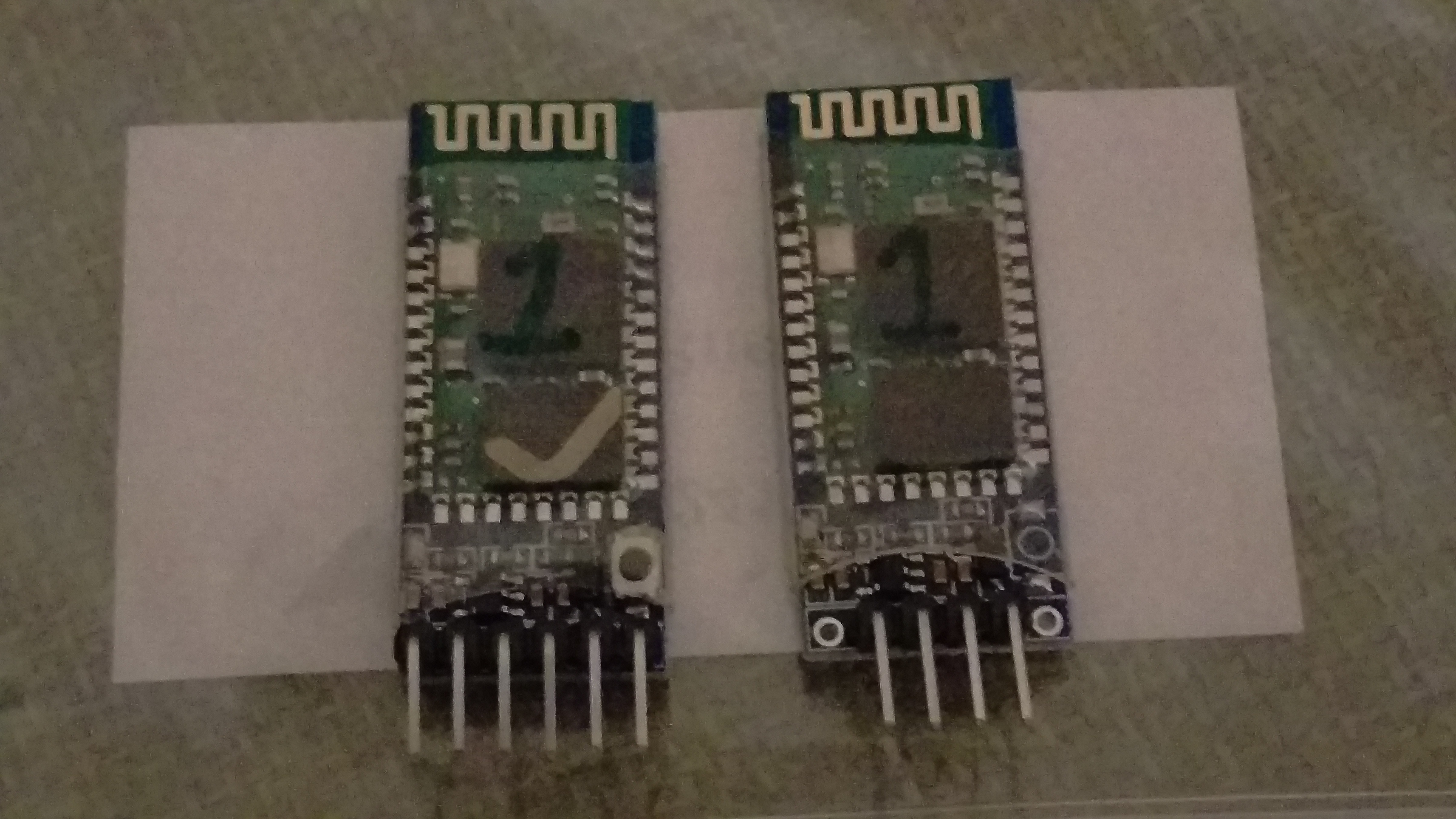
The HC-05 is recognisable by the 6 pins in place of 4 and also the small button next to the enable pin. Sometimes a HC-05 may be supplied with only 4 pins, but usually the button is present, otherwise you will need to interogate the board via a serial connection to find out which you have.
For this document I used four HC-05 and four HC-06’s. Initially we will connect them using a PIN code that is the same on all devices, then we will BIND them to only pair to specific slave units. The HC-06 are effectivly the slave units as there are limited commands availble, this in turn means the HC-05 we will be using as the master unit to initiate and connect to the slave units.
To configure the modules we will use an Arduino Nano. I had two just so I could carry out some tests and to confirm my instructions work and data can be passed between the two Arduinos. As the Arduino Nano only has one serial port, we will configure a second software serial port. I will give the code here, but if you are having issues with the Software serial, I suggest you go Google it, there is a lot of information already present on the internet.
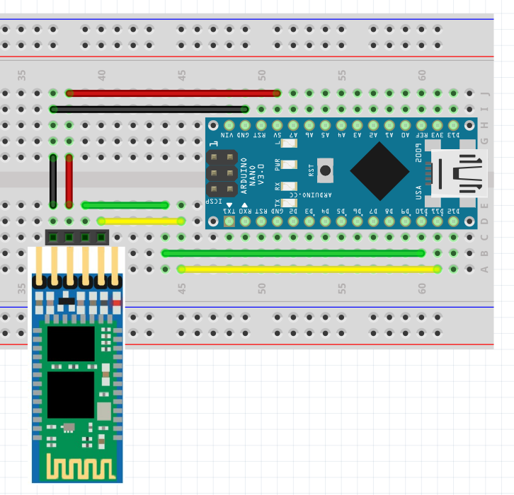
As you can see in the Fritzing diagram above, the HC-05 and HC-06 only need 4 pins, although I have used the HC-05 in the above diagram showing all 6 pins. Wire up the HC-06 (the 4 pin version) as above and then load this sketch onto the Arduino.
#include <SoftwareSerial.h>
SoftwareSerial btSerial(10, 11); // RX, TX
void setup() {
  Serial.begin(9600);
  Serial.println("HC-06 Configuration");
  mySerial.begin(9600);
}
void loop() {
  if (btSerial.available()) {
    Serial.write(btSerial.read());
  }
  if (Serial.available()) {
    btSerial.write(Serial.read());
  }
}
With this code loaded the red LED on the bluetooth should flash quite quickly, this indicates the module is not connected to anything via bluetooth. Open up the serial monitor and set the speed to 9600, and more importantly set the line return to ‘No Line Ending’. The HC-06 reacts to commands en-bloc where as the HC-05 expects a carriage return and line feed (CR/LF). I have no idea why, but this is the way they work so we have to work with it.
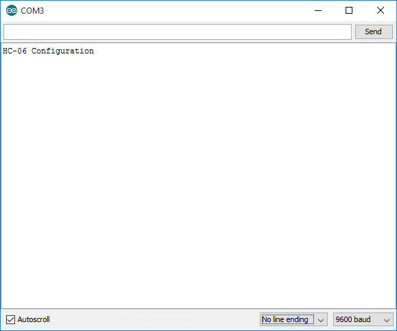
In the command window type the command AT and press enter, you should receive an OK back from the HC-06. If this is not the case, check everything again because this is how they should work out of the box! IF you are using a HC-06 unit that you had lying around, there is a chance the port speed is not the standard speed, so go through all the alternatives and one of them may give you a response.
Now we have confirmed the unit is available and working we are going to enter three commands, the unit name, the unit PIN for connections, and the unit speed to be used once connected. At the minute we are using 9600, but you may want to increase or lower this speed. I’m going to use 115200, the maximum speed, for our connections. After each command you will receive a confirmation but not a line return as you see in the screen shot below.
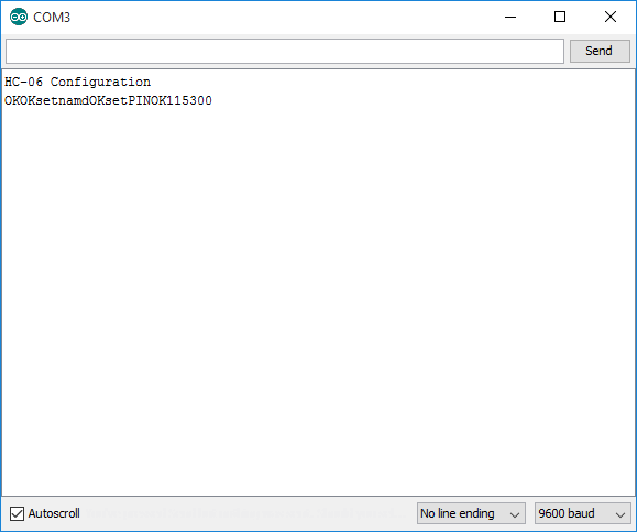
The first command we enter is AT+NAMEHC-06-1. This will set the name to HC-06-1
The second command is AT+PIN1234. This sets the connection pin to 1234.
And the last command is AT+BAUD8. This sets to line speed to 115200
To read up more on these commands Google HC-06 AT Command set and you should find the information. At this point we have configured the HC-06, now we can configure the HC-05. If you have a second Nano, connect the HC-05 and your PC to the second Nano, wired the same as the HC-06. You can use the same code but you need to change one line as the programming line speed of the HC-05 is 38400, not 9600. Don’t forget to upload this to the Nano!
#include <SoftwareSerial.h>
SoftwareSerial btSerial(10, 11); // RX, TX
void setup() {
  Serial.begin(9600);
  Serial.println("HC-05 Configuration");
  mySerial.begin(38400);
}
void loop() {
  if (btSerial.available()) {
    Serial.write(btSerial.read());
  }
  if (Serial.available()) {
    btSerial.write(Serial.read());
  }
}
Remove the power jumper to the HC-05 from the solderless board, press the button at the base of the HC-05 and hold it in then re-insert the power/vcc jumper. The LED on the HC-05 will now flash on and off, but slowely, you are in programming mode.
Open up the console but this time set the line ending to ‘Both NL & CR’, leave the speed as 9600. The HC-05 as I said previously can support a lot more commands. If we start with the basic AT command we can confirm connectivity, so enter AT and press enter. If we receive an OK then all is good and we can move on. As we need to pair the two devices, even if you are only using one Nano you need to have the HC-06 powered up, although the serial connection from the software serial now goes to the HC-05.
- The first HC-05 command is once again to set its ID: AT+NAME=HC-05-1
- The second is the PIN: AT+PSWD=1234
- The third is the port speed once we are connected: AT+UART=115200,1,0
The commands are slightly different from the HC-06 and you will notice that as you enter the commands the responses although are only OK are sperated by line returns, making it easier to read.
Now we have a few more commands:
- Set the unit to be a master and intiate connections: AT+ROLE=1
- Remove all previously paired devices: AT+RMAAD
- Just to check we enter this command and it should return a 0 to show no devices: AD+ADCN?
At this stage we can get the devices to pair, so remove the power to the HC-05, wait a few seconds and supply power but do not press the configuration mode button. Give it about 30 seconds and the two units should pair. You will tell when this happens as the light pattern will change from a fast flash to steady on with occasional flashes. Once the units are paired, we need to go back into config mode and do some more changes. So remove the power supply to the HC-05, hold the config button and re-connect the power supply. Back in the serial monitor check we have connectivity with the AT command and then proceed to this next set of instructions.
- Enter AD+MRAD? and take a note of the reply, which will include the MAC address of the last paired device.
- Take the reply and enter it with the AT+BIND=1234,12,abcdef The reply to the previous command has colons in it, you need to change this to commas as shown here.
- Now the command AT+CMODE=0 which tells the unit to only connect to the address it has been bound to with the BIND command.
- Finally we enter the AT+INIT command and the two devices will connect and we are done.
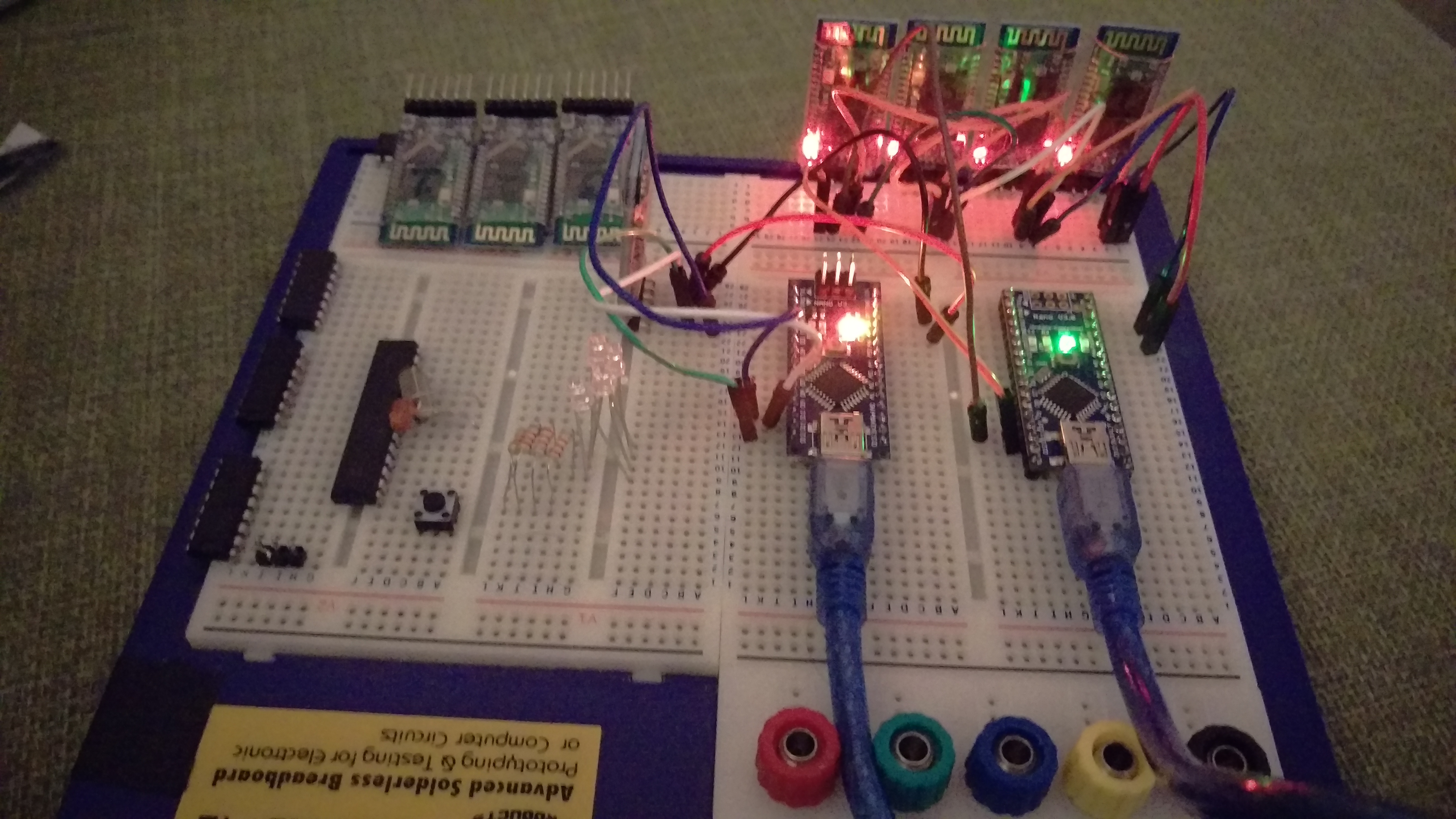
To confirm functionality we can set the port speed for the software serial port on the two Nanos to 115200 and then open up a Serial monitor session on one and a PuTTY or similar session on the second COM port and type back and forth. Congratulations they are paired to each other and can be used for your projects. In the photo below you can see 4 HC-06’s powered on and one HC-05, the HC-05 will now only pair to it’s matching HC-06 unit.
One thing to note is the state pin on the HC-05, this will allow you to see if the bluetooth unit is connected or not. If you use this code below and connect the State pin to Pin 9 on the Nano the onboard LED will light up when the bluetooth link is up, or go out when it is down. If you remove power from the HC-06 it will take about 5 seconds for the link to timeout on the HC-05 and the LED to also go out.
#include <SoftwareSerial.h>
SoftwareSerial btSerial(10, 11); // RX, TX
void setup() {
  Serial.begin(9600);
  Serial.println("HC-05 Configuration");
  btSerial.begin(115200);
  pinMode(9,INPUT);
  pinMode(13,OUTPUT);
}
void loop() {
  if (btSerial.available()) {
    Serial.write(btSerial.read());
  }
  if (Serial.available()) {
    btSerial.write(Serial.read());
  }
  if(digitalRead(9) == LOW) {
    digitalWrite(13,LOW);
  } else {
    digitalWrite(13,HIGH);
  }
}
Here are the links to a few sites I used for reference: